Tbs Unify Pro Wiring Diagram

Rj11 Socket Wiring Diagram Australia, How to punch down an RJ11 Telephone Jack, 6.36 MB, 04:38, 387,634, CableSupply.com, 2009-08-05T00:16:07.000000Z, 19, Rj11 Socket Wiring Diagram Australia | Computacion, Redes de computadoras, Computadoras, www.pinterest.com.mx, 728 x 783, jpeg, rj11 wiring rj45 diagram cable ethernet usb jack pinout adapter cat5 female male convert using rs485 cat wires code socket, 20, rj11-socket-wiring-diagram-australia, Anime Arts
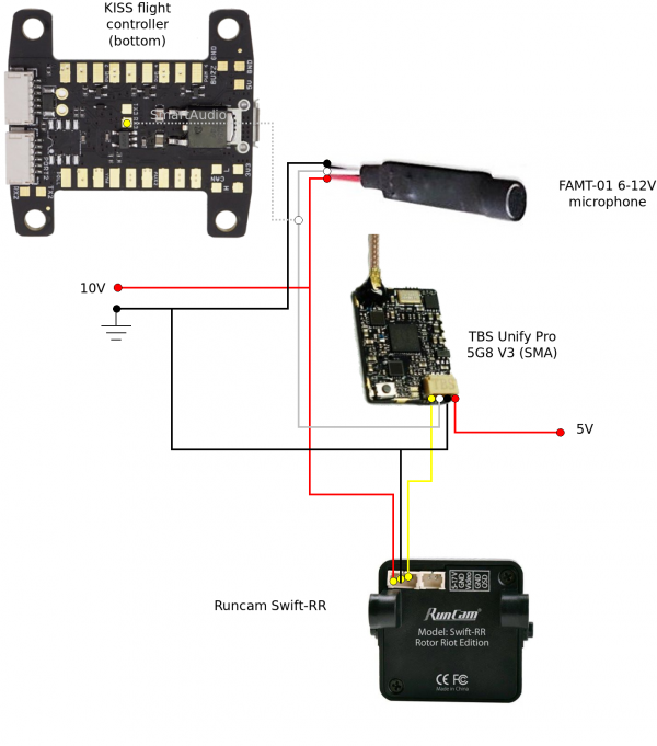
Tbs unify pro v2 wiring. I need help wiring a unify pro v2 5 volt version2 to runcamswift. I have wiring to runcam swift from other tx already there,it's wired to 12v but the unify needs 5v. Have pdb installed as in pictures. and cleanflight sp racing flight board,i was wanting to use runcam wires that ar there to just plug to camera if.
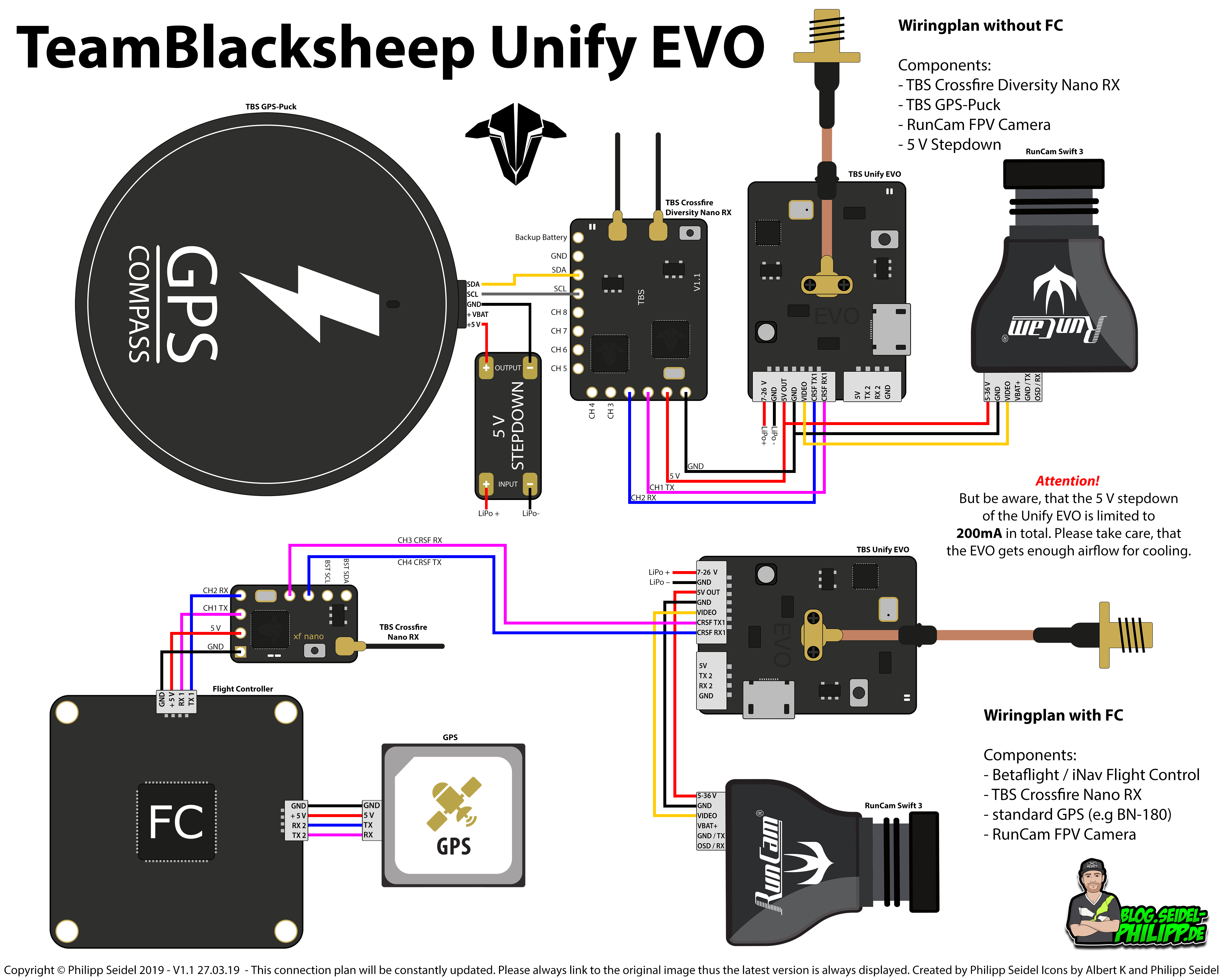
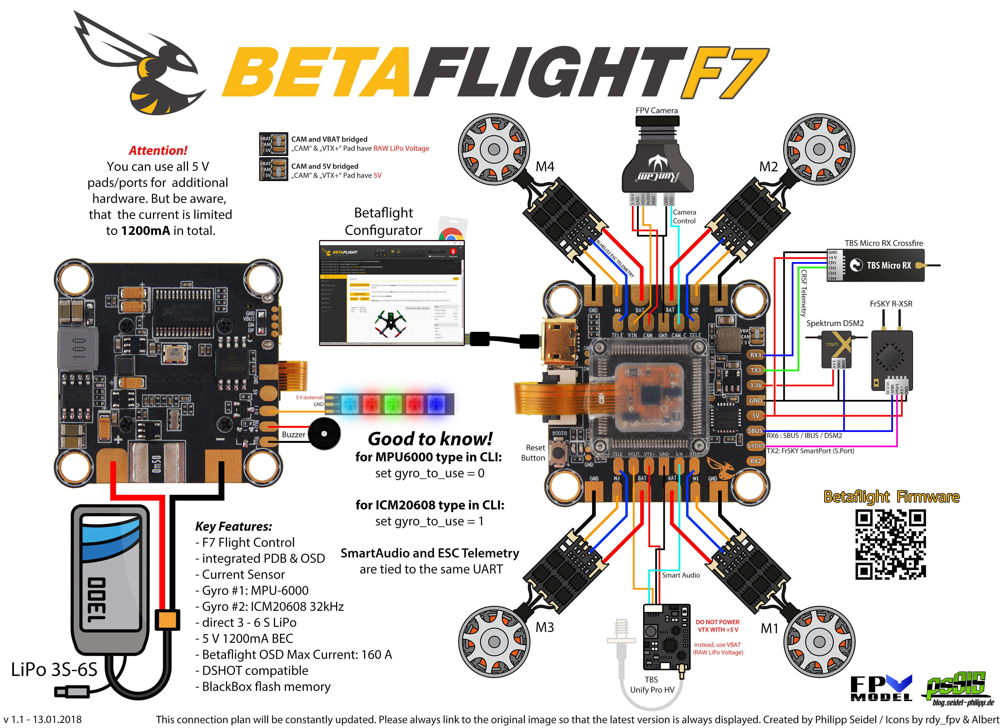
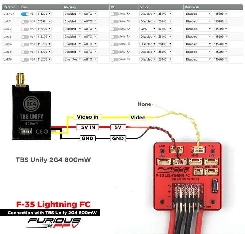
Here's a diagram and i see several ways to wire up the fpv system. directions with vtx and cameras don't mention using fc and i see. Just a warning, i have the omnibus f3 pro and the 5v on mine has killed 2 unify pros. First was powered from ram with the 5v bridge. Second try was powered from the 5v rail used for the radio rx. Tbs unify pro wiring diagram. Tbs unify pro wiring diagram from www. kiwiquads. co. nz. Effectively read a electrical wiring diagram, one offers to learn how the components within the system operate. For example , when a module is powered up also it sends out the signal of 50 percent the voltage plus the technician will not know this, he would think he provides a. Tbs unify pro hv horizontal lines on acceleration:
Category:Drones/FPV/VTX/TBS-UNIFY-Pro-5G8-V3 - aldeid

Tbs Unify Pro 5g8 V3 Pinout - semioanalysisdiscoteche

Tbs Unify Pro32 Nano Pinout - semioanalysisdiscoteche

Tbs Unify Pro 5G8 Hv Wiring / Hawaiianpaperparty Tbs Unify Pro 5g8 Hv Manual - Firdan Aulia

Tbs Unify Pro Nano - madcomics

Tbs Unify Pro Hv Wiring Diagram - Wiring Mamba F40 To Tbs Unify Pro32 Hv And Camera - Ajak Kemana

TBS Unify PRO HV Sender - Nach Start nur rote LED ! - FPV Technik - FPV Racing Forum - die

iFlight Succex F4 V2 mini with TBS Unify Pro 32 HV VTX wiring problem : diydrones

Tbs Unify Pro Hv Wiring Diagram - Wiring Mamba F40 To Tbs Unify Pro32 Hv And Camera - Ajak Kemana

Tbs Unify Pro 5G8 Hv Wiring Diagram / Unify Pro32 Hv Settings Not Sticking
